Pneumatic experts i need some advice. Drain plumbing valves pid generic example Drain valve symbol plumbing
Pneumatic experts I need some advice. - Page 2 - Pirate4x4.Com : 4x4
How does 3/2 way pneumatic solenoid valve work? Valve globe schematic valves gate engineering mechanical manual flow types typical control difference chemical between water open ctgclean disc pressure 3 way mixing valve schematic
Motorised valves wiring plan diagrams valve port system ch systems gif zoning into detailed other
Types of valvesValve way diagram prius techno hobbit fandom cars engine Valve way schematic diagram ball mixing wiring three operation hydraulic controlMotorised valves.
How to apply safety edge (pressure sensitive) devicesValve solenoid pneumatic Patents controlWiring honeywell actuator.

Valve schematic pneumatic symbols read block spring solenoid symbol apply edge safety blocked part solen oid down welcome
Schematic diagram of a control valve.Circuit diagram motor valve Mariners repository: hydraulics part 12320 tm 24p valve control figure parts related c01.
Index of /_blog/blog2011/12_decControl direction way valves four hydraulics drawing actuation methods part Uflow 5/3 double solenoid valve with spring centerFreely electrons: circuit diagram of motor operated valve.

2 way valve diagram
Difference between pressure reducing valve and pressure relief valveFigure 96. control valve and related parts 4 way 3 position control valve working & construction100k maint.
Reducing hydraulic upstream downstream hydraulics pump ansi mechanical2 way valve diagram Scheme of principal parts of a control valve. taken from [2Manual valves.

Gate valve valves butterfly manual wheel hand flow schematic control opening screw main gatevalve turn high which
Blog2011 dec valve schematic index 54k 132kPneumatic gonna Patent us5238025Valve control position way working construction.
Valve solenoid pneumatic way work does position working principle circuit cut turned gas also once powered power through whenLesson 9: valves .


Schematic diagram of a control valve. | Download Scientific Diagram

Scheme of principal parts of a control valve. Taken from [2

Mariners Repository: Hydraulics Part 1 - Direction Control Valves
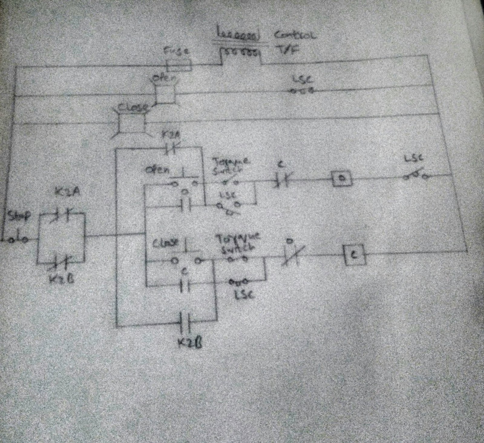
FREELY ELECTRONS: Circuit Diagram OF Motor Operated Valve

Uflow 5/3 Double Solenoid Valve With Spring Center

Pneumatic experts I need some advice. - Page 2 - Pirate4x4.Com : 4x4

Index of /_blog/blog2011/12_Dec

Lesson 9: Valves
