Adder bit four diagram parallel block ripple carry circuit binary My technical articles: necessity of hardware description language Bit adder parallel arithmetic binary circuits electronics digital fig learnabout
Binary Adder and Parallel Adder - Electrical Engineering Stack Exchange
Adder bit parallel subtractor logic diagram four circuit binary using carry block ic Adder bit parallel diagram technical articles block Digital logic
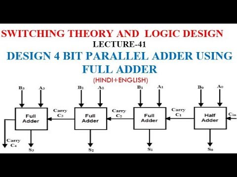
😊 four bit parallel adder. 4 bit binary adder circuit / block diagram
Adder binary adders electrical4u circuitsFull adder circuit diagram Adder subtractor bit circuit add sub overflow complement logic detection carry addition designing control zero digital line questions find computerLet's learn computing: 4 bit adder circuit.
Parallel adderWhat is parallel binary adder? Adder parallel addersAdder parallel binary serial bits gif stack first results.

Adder bit parallel four circuit diagram block
Binary adder and parallel adderAdder subtractor bit carry verilog make circuit diagram ripple using binary 4bit want geeksforgeeks hdl source output 聰明人求知心切 10+ adder circuit diagramBinary adder and parallel adder.
Adder circuit combinational ha sequentialAdder serial flip flop parallel circuit binary bit logic flipflop use clock carry numbers sum construct two electronics which stack Parallel adderAdder half boolean implementation.

😊 four bit parallel adder. 4 bit binary adder circuit / block diagram
4 bit parallel adder😊 four bit parallel adder. 4 bit binary adder circuit / block diagram Adder parallel bit diagramDesign of parallel adder.
Adder binary parallel bit logic diagram circuit electronics betweenBinary arithmetic circuits Adder xor ripple transistor pengertian rangkaian kombinasiCombinational and sequential design of a 4-bit adder. (a) ha circuit.

Circuit adder bit diagram logic computing learn let
Adder parallel multisim .
.


Combinational and sequential design of a 4-bit Adder. (a) HA circuit
😊 Four bit parallel adder. 4 bit Binary adder circuit / block diagram

Parallel Adder | Electrical4U

Parallel Adder

Design of Parallel Adder

Let's Learn Computing: 4 bit Adder Circuit

Full Adder Circuit Diagram

Binary Arithmetic Circuits
