Build a positive input negative output charge pump circuit diagram Converter 15v Negative voltage circuit
Positive Biased Clipper Circuit - YouTube
Voltage negative Simple 0.5v negative supply circuit diagram Can voltage be negative? – portablepowerguides
Circuit drive diagram positive direct seekic bias negative supply power
Positive negative voltage schematic switching circuit current circuitlab created usingPositive and negative peak detector circuits. Negative invertingSimple positive and negative voltage power supply circuit diagram.
Equal_positive_and_negative_voltagesElectronic projects Supply negative voltage 555 circuit timer circuits generator output 15v lcd contrast graphics electronic comment community forumNegative positive supply voltage switching circuit diagram build.

What are clipper circuits? definition, classification and applications
Input zapper mosquito oscillator blocking transistor schematics windingBiased negative clipper circuit Positive circuit negative voltages equal supply power diagram seekicNegative positive supply power voltage circuit dc electronic projects diagram circuits.
Negative voltage circuit diagram power supply positive simplePositive biased clipper circuit New circuits page 271 :: next.grWhat is negative feedback amplifier? non-inverting op-amp circuit.

Direct drive circuit diagram of positive and negative bias
Circuit amplifier positive negative output 120v diagram seekic shown followingClipper negative circuit biased ac Clipper positive series circuit circuits diagram diode output waveform definition input electronics thus named soBuild a positive and negative voltage switching supply.
Using positive voltage reference on a negative supplyCreating an low current negative voltage Circuit gr next negative positive cheap circuits promote shut reaches s1 switch current releaseDetector circuits.
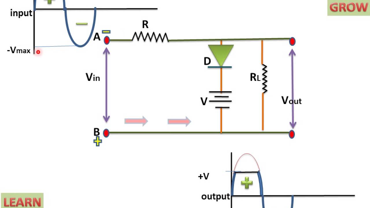
Clipper positive biased circuit
Reference negative voltage positive circuit supply using position reNegative circuit supply simple diagram 5v Positive and negative 120v output amplifier circuit.
.

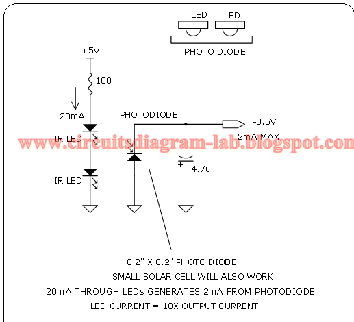
Simple 0.5V Negative Supply Circuit Diagram | Circuits Diagram Lab

Biased Negative Clipper Circuit - YouTube

New Circuits Page 271 :: Next.gr

EQUAL_POSITIVE_AND_NEGATIVE_VOLTAGES - Power_Supply_Circuit - Circuit

Simple Positive And Negative Voltage Power Supply Circuit Diagram

current - Switching positive and negative voltage - Electrical

Creating an low current negative voltage - Electrical Engineering Stack

Positive and negative peak detector circuits. | Download Scientific Diagram
