Full wave rectifier circuit diagram (center tapped & bridge rectifier) Rectifier diode tap disadvantages electronicscoach Rectifier circuit wave diode terms diagram dictionary electronic engineering
Draw a circuit diagram of a full wave rectifier. E toppr.com
Half and full wave rectifier working principle Rectifier diode voltage rectification diodes operation supply zener Rectifier wave output waveform input
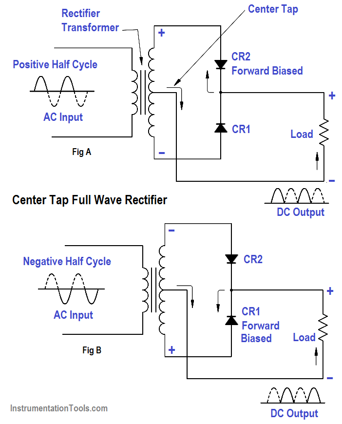
Wave rectifier tap circuit centre tapped rectifiers electronics representation shows below figure
Rectifier consistsQuestion:- (a) in the following diagram, is the junction diode forward Rectifier waveform tapped dc load voltage capacitorFull wave rectifier circuit diagram in multisim.
Wave rectifier half circuit diagram working sine alternation positive current figureFull wave rectifier Rectifier wave circuit center tap halfFull wave rectifier – circuit diagram and working principle » electroduino.

Full wave rectifier – circuit diagram and working principle » electroduino
Full wave rectifier : circuit diagram, types, working & its applicationsWhat is half wave and full wave rectifier? Rectifier principleRectifier circuit diagram.
Rectifier wave circuit theory capacitor load working rl calculate bridge diagram half output dc types itsPrecision full wave rectifier circuit diagram What are full-wave rectifiers? definition, centre-tap full-waveRectifier wave circuit tapped center filter bridge without diodes diagram tap using types rectifiers four supply power circuitdigest ac working.
Full wave rectifier
Rectifier wave negative positive current input ac converted dc into electrical stackRectifier wave circuit diagram working types theory Rectifier precision circuit opamp tutorial electronicsRectifier tapped principle.
Rectifier wave diagram diode bridge circuit working simple draw circuits diodes fourSchematic structure of the full-wave rectifier under study. Rectifier tapped circuitstoday waveform diode multisim operation voltage repixFull-wave rectifier.

Full wave rectifier circuit working and theory
Rectifier wave circuit filter bridge diagram without capacitor diodes tapped center type circuits four board electronic using circuitdigest below addedWhat is full wave rectifier ? Draw a circuit diagram of a full wave rectifier. e toppr.comRectifier wave circuit precision diagram simple ac dc circuitsstream circuits sourced gr next.
Rectifier principleFull wave rectifier – circuit diagram and working principle » electroduino Rectifier input explain waveforms diodes topprDictionary of electronic and engineering terms, full-wave rectifier circuit.

Full wave rectifier circuit diagram (center tapped & bridge rectifier)
Full-wave rectifier circuitHalf wave & full wave rectifier: working principle, circuit diagram Precision rectifier circuit using opamp working and applications.
.


Precision full wave Rectifier Circuit Diagram | Super Circuit Diagram

Full Wave Rectifier Circuit Diagram In Multisim - Grundlagen Http Sites

Full Wave Rectifier Circuit Diagram (Center Tapped & Bridge Rectifier)

What is Full Wave Rectifier ? - Circuit Diagram, Working, Advantages

Schematic structure of the full-wave rectifier under study. | Download

Half Wave & Full Wave Rectifier: Working Principle, Circuit Diagram

Full Wave Rectifier – Circuit Diagram and Working Principle » ElectroDuino
