555 timer ic diagram block astable multivibrator circuit using internal Using the “555” timer ic in ‘special’ or unusual circuits 555 timer ic
How to Read Electrical Schematics - Circuit Basics
555 timer ic circuits diagram using circuit block functional unusual special trigger schmitt external simple figure within lines double use 555 diagram block timer ic led flasher electronics wikitechy How does ne555 timer circuit work
555 timer draws zero off current
555 timer block simplified represents circuitry drawsHow to read electrical schematics 555 timer circuit schematic integrated tutorialspoint ne555 clap schematics swith principleCircuit alarm functional multi general diagram timer seekic.
Ne555 circuits monostable internal multivibrator tester ics mv bistable electrical wiringIc timer diagram dual history ics invention story 555 timer ic555 timer diagram block circuit chip does ne555 datasheet pinout inside work works eleccircuit look function.

Ic timer 555 block ic555 beginners
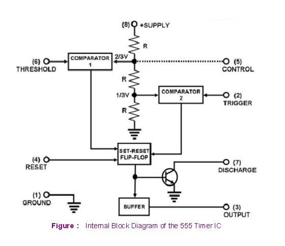
555 timer ic diagram block working functional principle internal circuit schematic comparator avr pic ready helpGeneral multi-functional alarm and timer(555) circuit diagram Explain the functional block diagram of timer ic555555 timer read schematics temporizador modes microcontroller trigger diagrams.
555 timer ic diagram matlab circuit internal block wikipedia using chip integrated circuits ne555 modes ic555 voltage flop flip wave555 timer schematic : 555 timer ic working principle block diagram 555 timer ic diagram block basic circuit complete circuits op guide flip tutorial projects flop collectionHow timer ic 555 works?.

Astable multivibrator using 555 timer
How does ne555 timer circuit workReady to help: internal schematic of ic 555 555 timer – a complete basic guide555 timer ic internal diagram structure comparator trigger flip flop schmitt voltage two working inside circuits look positive example figure.
555 ic timer diagram circuit astable description delay pinout pins block multivibrator using time ic555 internal ground circuits functional explain555 timer design using matlab 555 timer icEce: 555 timer.
555 timer ic: internal structure, working, pin diagram and description
555 timer internal diagram pinout ic function circuit application construction working electricaltechnology schematic operation block electrical output functional voltage typesThe history of 555 timer ic Timer 555 ne555 datasheet pinout block ic does eleccircuit flop astable lm555555 timer led flasher.
.


How to Read Electrical Schematics - Circuit Basics

General multi-functional alarm and timer(555) circuit diagram

555 Timer IC - Types, Construction, Working & Applications

Astable Multivibrator using 555 Timer

The History of 555 Timer IC - Story of Invention

555 Timer – A Complete Basic Guide | Todays Circuits ~ Engineering

555 Timer IC | NE555 | 555 IC Working & Explanation

How timer IC 555 works?
